CNC machining programs and CNC process
What is CNC machining
CNC-Computer Numerical Control. CNC machining programs are the software packages that used to manufacture parts on cnc machines. CNC machining is a subtract manufacturing technology. A variety of cutting tools are used to remove material from a sold block. Computer can control the tools to move along the tool paths in small increments. You can use CNC machines to manufacture almost every material, such as metal (steel, aluminum alloys, etc.), plastic (ABS, Nylon, etc.), foam, wood, stone, ceramic, and so on. On the market, there are many CNC machines. CNC milling machine, CNC lathe, plasma cutter, EDM (Electric Discharge Machining), Multi Spindle Machine, Wire EDM, Sinker EDM, Laser cutting machine, Water Jet Cutter are all considered as CNC machine. Industrial CNC machines are expensive, but there are also some desktop CNC machines. Usually desktop CNC machines are less weight, less precise and less rigid than industrial machines. And due to the lower stability and quality, these machines can machine soft materials, such as foam, wax, plastic, but they cannot manufacture hard material.CNC machining process
There are 4 steps to manufacture a part on CNC machines.Step 1. Design 3D models or 2D drawing with CAD software
The first thing is to design the files. It can be a 2D drawing or 3D model. For example, it can be a dxf format file or a stp format file. That depends on what part you want to manufacture. There are many software packages can be used to do that. You can read <How to learn 3D CAD software> to get more information. Note: Compared to 3D printing, when you design 3d models for CNC machining, there is more design restriction due to the nature of subtract technology.Step 2. Program
In this step, you need to convert the 2d drawing or 3d model to G-Code. Of course, for some simple design, you can program manually too, but the most popular method is to do that using CAM software.Step 3. Set up the parameter via the control software (interface software)
Place the block of material on the build platform of the machine and mount it with jigs. In this step, for accurate parts, the key is the precise position and alignment of the block. Usually you can use special tools (touch probes) to do that. Of course, there are some other methods. After that, you need to set up some parameters via the interface software. For example, the length of tools, original point, speed, etc.Step 4. Manufacture the part
The last step is to turn on the machine and manufacture the parts. Usually for safety, you need to manufacture the first part step by step, and run the program(G-Code) line by line. In a word, be careful to avoid any damage on the machine. Some CAM software packages allow you to simulate the machining process before you turn on the machine, but you still need to be careful.CNC machining programs type
There are 3 types of CNC machining programs.1. CAD software/CAD programs
CAD software/CAD programs are used to create 2d drawing or 3d models.Remember,the design restriction is different from 3d printing even you use the same CAD software package. Read <How to learn 3D CAD software> to get more information.2. CAM software/CAM program
CAM-Computer-Aided Manufacturing. Traditionally,CAM software can be considered as a program that is used to generate G-Code from 2d drawing or 3d model. CNC machines cannot understand 2d drawing or 3d model directly, but they can understand G-Code, so CAM software is the middleman between the 2d drawing/3d model and the CNC machine. In the CAM software, you need to choose cutters, set up cutting parameters, and then general G-Code via a post processor (the post processor may be different due to different control systems on your machine). That is a simple understanding of CAM software. In fact, CAM is more than that, but we won’t talk much here. Some CAM software packages: CAMworks, Fusion360, Hypermill, HSM, Mastercam, Powermill, UG, SolidcamCAM, SprutCAM, WorkNC, etc. Many software packages have combine CAD and CAM function together, such as CATIA,UG,etc. And even some CAD software packages don’t have CAM function, sometimes there are CAM plugin for these CAD soft wares too. If you want to manufacture parts with CNC machine/router,it is necessary to learn a CAM software.3. Control software
In most cases, it is built into your CNC machine, especially industrial CNC machines. You just need to know how to set up parameters, and usually it is not complex. But you must be careful when setting up parameters. These are some interface software: FANUC, Sinumerik(Siemens), Heidenheimer, Mitsubishi, Haas, Mazak, Cincinnati, Mach3, Mach4, LinuxCNC and so on. But most of them are expensive.
Cheap CNC machining programs
MeshCAM Commercial
MeshCAM is software available for Non-Machinists. It is compatible with most common 3D format files, STL and DXF files.MeshCAM has a built-in post processor that will be used to produce G-Code.The following post processors are included: Mach 2/3/4,Linux CNC,Fanuc Compatible, Haas,Shopbot,GRBL,Roland.It supports windows vista,7,8,10 and Macs with OSX 10.9 or higher.Fusion 360 Commercial
Fusion 360 is a cloud-based 3D CAD/CAM tool. CAM for Fusion 360 includes 2-, 2.5-, & 3-axis machining and that allow you to generate G-Code to manufacture your components or create prototypes.CamBam Commercial
You can use this application to create G-Code from 2D DXF or 3d models. There is free, fully evaluation session. And after the evaluation period expires, you can still use it to generate G-Code, but limit to 1000 lines. CamBam 0.9.8 can run on windows xp up to windows 10.Sheetcam Commercial
It is a low cost but feature CAM package. It is suitable for routing, milling, waterjet, plasma, oxy-fuel cutting and laser. SheetCam contains a wide variety of post processors: Mach3, CandCNC, etc. And it allows you to create your own posts too.Mach3 and Mach4 Commercial
It is affordable CNC control software package.And it is one of the most popular CNC machining programs.Mach3 can work on most pc’s with windows system. It allows you to use your pc to control the motion od motors (servo and stepper) by processing gcode. It is primarily designed for the parallel port that has become obsolete. Before buy a license, you can try the software, and there is no limitation. Mach4 will need a plugin and motion control board to operate a CNC system. Now PMDX and Vital Systems have available plugin for motion control. If you want to run from parallel port, you can buy the parallel port legacy plugin, but it is not a good method to use the parallel port. The license only works for the computer that you supply the ID at checkout.
LinuxCNC Open source
LinuxCNC is a CNC control software package that runs on Linux. It can be used to control lathes, milling machine, laser cutter,3d printer, robot arms, hexapods, plasma cutters, and more. It is a free tool of cnc machining programs.G-Code Generator
What's G-Code?
These days, computer numerical control (CNC) machines range from 3D printers to lathes, mills, and engraving machines that use lasers, plasma, or water jets. Computer control manages tool movements, spindle speed and coolant flow for CNC lathes and mills, and extrusion and bed temperatures for 3D printers. Over time, a common computer language evolved for CNC: G-code. G-code is the not-so-secret sauce that runs a 3D printer. Based on your STL model and your settings, your slicing program decides how to make your part. It takes into account layer thickness, infill percentage, support, adhesion, extrusion, and bed temperature to generate a G-code recipe for your part, which can be understood by your printer. Each motion of the printer is given, for example, to trace the perimeter, cross-hatch, or trace interior holes. Temperature control, extrusion, and retraction are also given in G-code. For CNC machining and cutting, G-code starts the cutter, controls coolant, and moves the machine to execute a path or contour of engraving, milling, or cutting. Alphabet Soup A language of one-liners, many G-code commands do begin with the letter G, but in fact, all letters of the alphabet are used. Codes beginning with G, M, X, Y, and Z are the most common. In 3D printing specifically, E and F are used for extrusion and feed rate. If you see something like GXX, that’s a preparatory code, and many of them move the machine. MXX codes are the miscellaneous commands, controlling things like coolant, spindle speed, fans, and heaters. X, Y, and Z are coordinates.What's a G-Code Generator?
Generating G-code means creating a full description of how to make something with a machine. Originally, G-code was hand-coded – imagine that! For a simple machined part, this can work. With an understanding of machining, knowledge of the relevant G-codes, and some copy and paste, anyone can create the full G-code recipe for a machined part. Slicers (3D Printing) 3D printing creates smooth, attractive parts because it uses a small nozzle to extrude thin layers of plastic. Even a small printed part can have hundreds of layers, each with hundreds of small motions, meaning tens of thousands of lines of G-code. For that kind of recipe, hand coding is a problem. For 3D printing, G-code generators are called slicers because they “slice” an STL file into layers that can be extruded as an outline with cross-hatching or infill. A slicer also takes into account the extrusion temperature, fan, and speed requirements for running a particular material on your machine. Other Generators (CNC Machining) CNC machining may not have the thousands of steps of 3D printing, but it too can get involved. When cutting even a single pocket or through-hole, it takes several passes around the same path at increasing depths to make the complete feature. And even then, a finishing cut, removing a final layer of material, is typically used to get the best surface finish. Other details that are hard to add by hand are tabs. These small bridges or breaks in the contours of the part keep it attached to the parent material. A CNC router code generator can add these easily. Automating the creation of multiple passes, finishing cuts, and tabs are just some of the ways a CNC code generator simplifies the G-coding process.Generation
Because CNC machines perform repetitive operations, the same basic cycle can be repeated. Let’s take a look at some of the steps that go into creating G-code, which are automated by a g-code generator. 3D Printing After dividing an STL file into layers, the basic cycle for generating G-code for each layer is as follows: The basic cycle for generating 3D printing G-code is as follows: Identify the outlines, both exterior and interior, in order to determine what’s “inside” and “outside” the layer. Determine how infill will be laid within the interior of the layer. Create an optimized traversal of the layer’s extrusion for outlines and infill. Set the speed, extrusion, temperatures, and fan speed. Create G and M codes for the start and end. Convert the full traversal path into GXX movements, adding extrusion E and feed rate F. For more on how a slicer works, step by step, take a look at this DIY g-code generator on Instructables. CNC Machining Parts to be CNC milled are similarly divided into depths, where a cycle is repeated at each layer: Set exterior or interior for pockets or through-holes. Set the depth of cutting and passing required to produce the full contour height. Set the tool diameter or kerf (the cutting diameter of a laser, plasma, or a water jet). Set tool alignment to be inside or outside of the path. Set the spindle speed or cutting intensity. Create G and M codes for the start and end. Create positions for the path, including multiple passes at depth of cut to create the full contour. Convert the geometry into GXX motions. For more on how to create CNC G-code, take a look at this online course. G-Code GeneratorExamples
To give you a little taste, here are some sample G-codes. The following line homes X and Y: G28 X0 Y0; This one instructs a linearly interpolated movement using absolute X and Y coordinates: G01 X61.888 Y127.862 E19.90544; Here are two special codes for 3D printing: M107; (start with the fan off) M109 R245; (set the extruder temperature to 245 °C and wait) And here are two for CNC lathes and mills: M03; (spindle on, clockwise) M08; (coolant on) Thirsty for more? Check out our in-depth article on G-code examples. In our programming tutorial, we go even deeper with G-code commands.Generators
In fact, there are a plethora of G-code generators out there. For 3D printing, we have another article that lists the best 3D slicer software. One of the great things about 3D printing is that STLs are the standard input file for slicing. For CNC machining, the story is a little more complicated. First, there are tools that help automate the G-code creation while leaving the understanding of the geometry to the user. You can see an example with this Excel-based G-code generator and a related tutorial video. Next, we can start with a 2D source file, like a PDF, DXF, or an image. The program does the heavy lifting of interpreting the paths in the drawing or image. Some examples are Cut2D, FlowPath for water jet, DXF to G-code, and PixelCNC for images. There’s even an Inkscape G-code plotting extension for creating cutting programs from Inkscape designs. Last, the most sophisticated G-code generators are called CAM, or computer-aided manufacturing. These tools interpret a broad range of files, including 3D solid models, and use them to automate the full G-code creation process. See our review of the best CAM software tools for SolidWorks and AutoCAD.Generate G-code Using Inkscape
In last week's post we discussed how to create vector graphics from bitmaps in Inkscape. The third suggestion on why to do such a thing involved creating toolpaths for machines. As a natural continuation from last week, we're now going to talk about such toolpaths, called G-code, and how to generate those in Inkscape.What is G-code?
G-code is the most widely used programming language for controlling industrial machines such as mills, lathes and cutters as well as 3D-printers. G-code has many dialects or variants, but most (or all) adhere to certain common rules. A CNC mill interpreting G-code in real-timeStructure and Commands
Each new line (called block) in the G-code can be roughly regarded as a new command. Everywhere you look in the code you will mostly see letters with numbers behind them. These letters corresponds to different types of commands. The most important ones are arguably G (used in most movement commands), M (miscellaneous commands), X, Y and Z (the last three are used to define positions in the X,Y,Z space, absolute or incremental). A complete list of all of the letters with explanations can be found here. A list of the different G and M-codes can be found here and here.Example
A trivial example of a couple of blocks: G90 G21 G00 X1.1 Y1.1 Z1.1 G01 Z-1.0 F100 G01 X2.2 Y3.3 Z-1.0 F500 The first block does two things and is kind of a very simple setup block. G90 is the command that defines all coordinates as absolute with an origin as a reference. G21 defines all numerical values as millimeters. The second block makes the machine run rapidly to position (1.1,1.1,1.1) in the XYZ space from its current position. How fast this movement is done is defined in hardware. The third block moves the machine in the Z-axis to -1 with a rate of 100 mm/min. The last block moves the machine in a straight line to position (2.2,3.3) in the XY plane with a rate of 500 mm/min.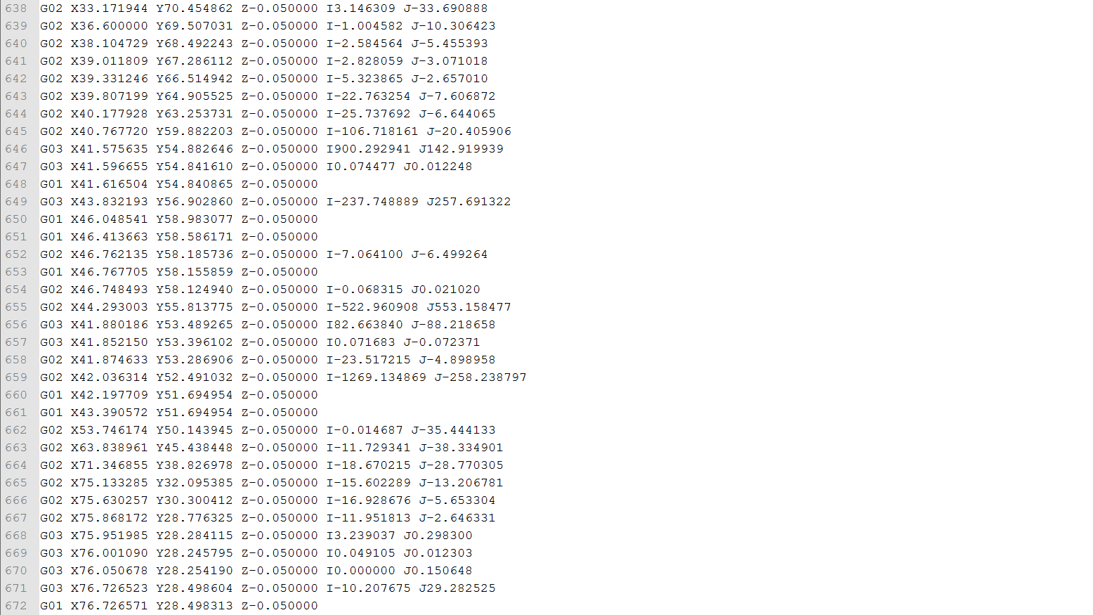 A snippet from an actual G-code file
Generating G-code in Inkscape
Writing G-code manually for more than a simple square would be practically suicide, so luckily we have programs which do this for us.Important Considerations!
When generating G-code this way it's important to know what kind of machine you're generating G-code for and how it interprets the code. Using Inkscape to generate G-code is NOT recommended when operating CNC mills, lathes, cutters or anything of that sort. For that it's too dangerous! For those kind of machines you should use more professional software, such as anything from Vectric. However, if you've made a machine on your own which need some kind of motion, such as a drawing machine or a laser engraver, generating G-code in Inkscape is both quick and easy.Gcodetools
You'll need an extension (that's what they call plugins in Inkscape) to be able generate G-code in Inkscape, and the only one that we're aware of which is capable of doing so is Gcodetools (yes, this forum thread is the closest you'll get an official page). It is far from perfect and poorly documented, but it does the job.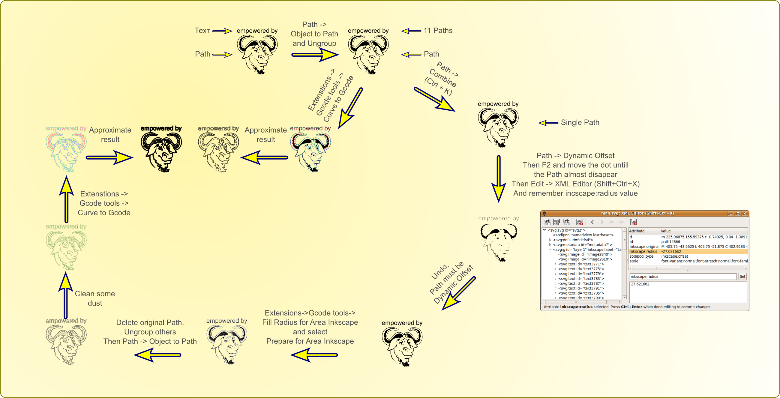 Gcodetools' main features according to the developer
Step-by-step Tutorial (by example)
In this example we will generate a toolpath for our laser engraver to engrave a drawing of a dinosaur. The way the laser engraver interprets the G-code is that it turns on the laser when the virtual Z-axis has a negative value and off when it's zero or positive.Preparations
Edit February 2018:First we follow the guidelines on Gcodetools' page to install the extension. The gcodetools extension is now included in Inkscape's default extension library. A dev version is also available from github if that's what you prefer. Since the drawing of the dinosaur is a regular bitmap image we need to trace the bitmap. Read this post to learn how to do this. The object needs to be in an own layer (click the link to see how to use layers). Just cut-paste it into a new one to be sure. We want to have control of how large the result will be in real life. Therefore we scale the object such that it is as large as we want it in millimeters (click the padlock icon or hold ctrl down and drag a corner to lock proportions). In this example we want it to be maximum 100 mm in either axis. Also, we position the object where we want it. We want it to be at least 10 mm away from the X and Y axes.
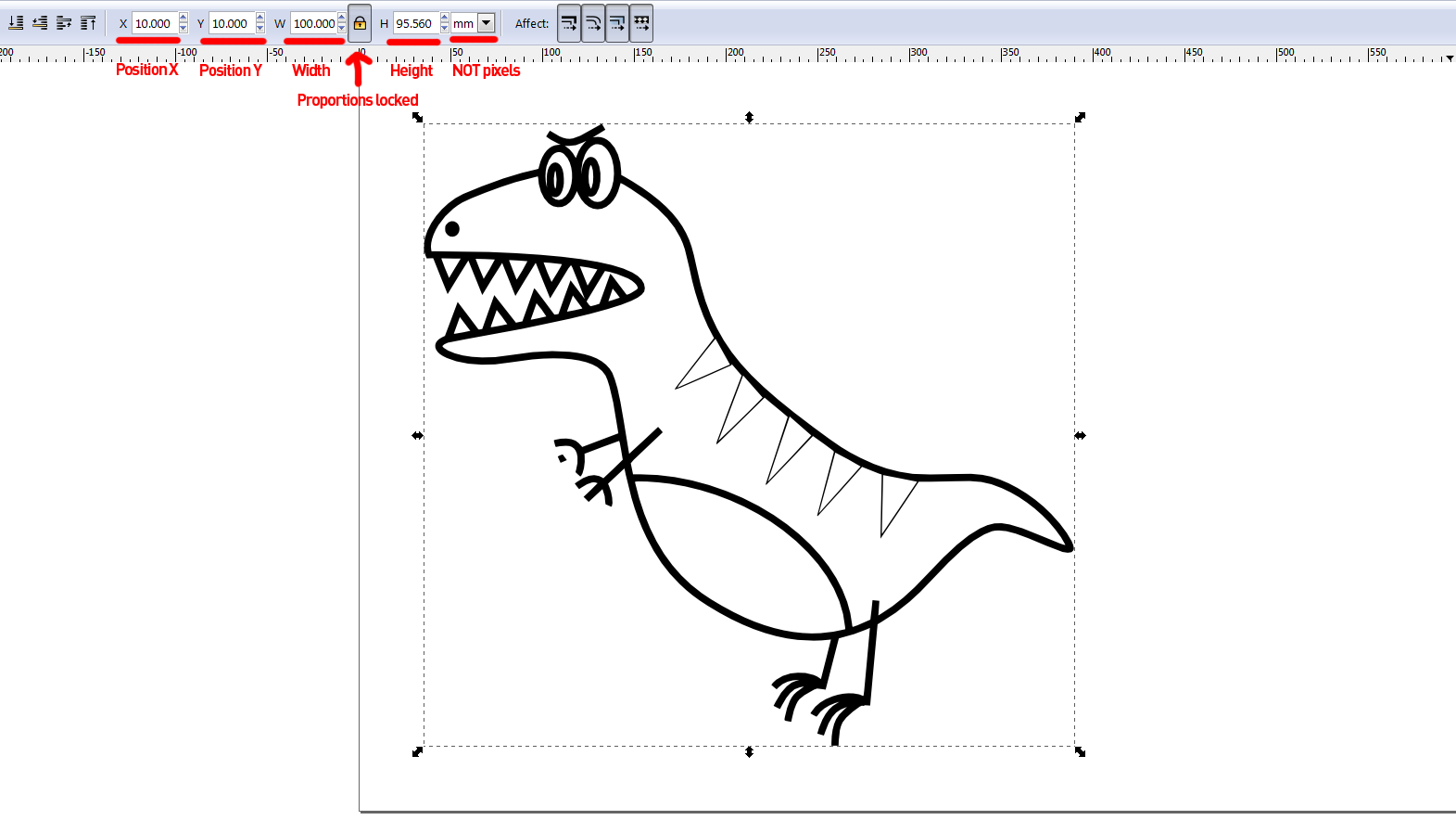 Scaling and positioning our dinosaur
If we select the object, we can see at the bottom of the Inkscape window how many nodes that exist along the path.
We have a rule of thumb that it should stay below 3000 (or 10000 with only straight lines) so that the G-code generation won't freeze up on us or take too long.
If you have too many nodes, simplify the object by pressing ctrl+L as many times as necessary until the node count is low enough.
Our dino is at 528 nodes, so we don't have to simplify.
Scaling and positioning our dinosaur
If we select the object, we can see at the bottom of the Inkscape window how many nodes that exist along the path.
We have a rule of thumb that it should stay below 3000 (or 10000 with only straight lines) so that the G-code generation won't freeze up on us or take too long.
If you have too many nodes, simplify the object by pressing ctrl+L as many times as necessary until the node count is low enough.
Our dino is at 528 nodes, so we don't have to simplify.
The Tools Library and the Green Thing
We need to choose a tool for the job, whether it's our actual tool or just a virtual one. If we click the Extensions menu, and under Gcodetools we click Tools library…, we get to the window with the same name. In all our appliances for this type of G-code generation (laser engraver and plotter) we have used the cylinder option. When pressing apply, an obnoxious green thing pops up in our drawing. We close the previous window and move the green thing away from obstructing our dino. This green square is part of the image and at the same time used to set up the G-code generation (weird, right!?). To change the parameters, we select the text tool and click on the numbers. Let's set the tool diameter to 1 (doesn't have too much to say, but it's best to not have it too big), the feed rate to 200 mm/min (in our case, this decides how strong the engraving will get) and the penetration feed to 10000 (just an arbitrary high number to quickly turn on and off the laser). We'll leave the rest as it is.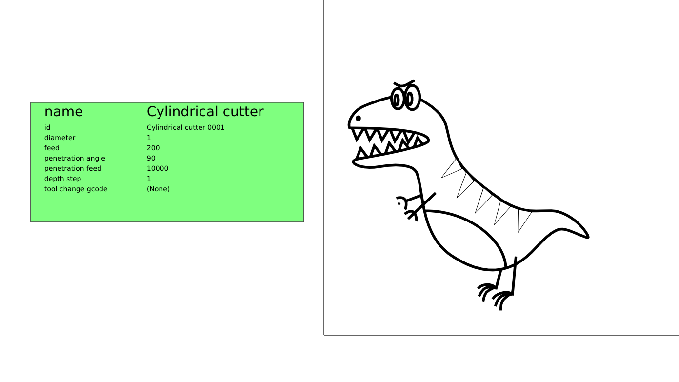 Dino is not happy about the green thing invading his space.
Orientation points
These are a bit cryptic, but we do need them. Select Orientation points… from the Gcodetools menu. In the window that pops up we select the top option, set the Z surface to 0, the Z depth to -0.1 (we just want it to barely go below zero to turn on the laser quickly) and the Units as mm. Then we click apply and close the window. It is best to leave those arrows with the numbers in parenthesis that pop up where they are and don't mess around with them.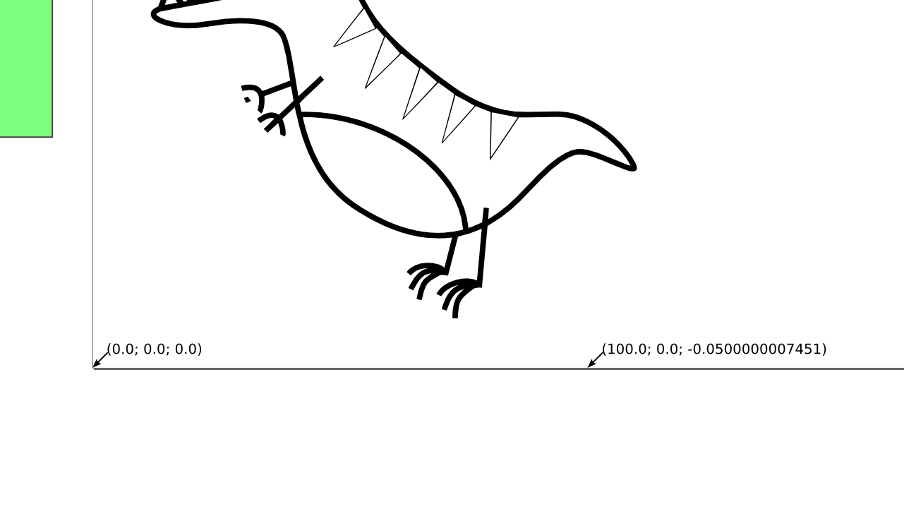 The mysterious orientation points
Path to Gcode
Now we are ready for the magic. In the Gcodetools menu we select Path to Gcode….There are four tabs in the window that pops up. We start in the Preferences tab. We name the file dino.ngc and places it in a convenient directory (e.g. C:\Users\Mads\Desktop). We set a low safe height such as 0.1 since we're not actually moving along the Z-axis at all. Units: mm and Post-processor: None. The rest is blank. Under Options we leave everything as they are by default. In the Path to Gcode tab we make sure Subpath by subpath is selected and that Sort paths to reduse (yeah, we know) rapid distance is checked. The rest is as it is by default. Make sure that only the object you want to generate G-code of is selected (in our case: the dinosaur) and make also sure that you have the Path to Gcode tab selected before pressing apply (you will, believe it or not, get an error message if you have a different tab selected). If we don't encounter any errors, our dino will look like this after the generation process is done: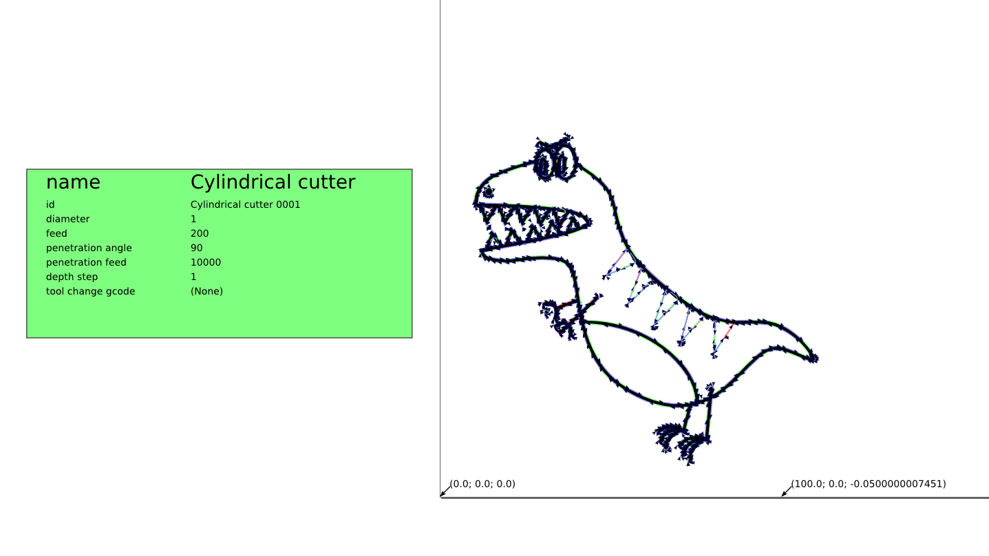 The G-code generation is done! Notice the arrows along the dinosaur.
Visualize the G-code
To confirm that the newly generated G-code will result in something that looks remotely like our dino, we need something to visualize the G-code. There are probably many programs out there which can do this, but we like to use OpenSCAM. Here we can see how long it takes to perform the whole job as well as see how the machine will travel along the path in real or accelerated time.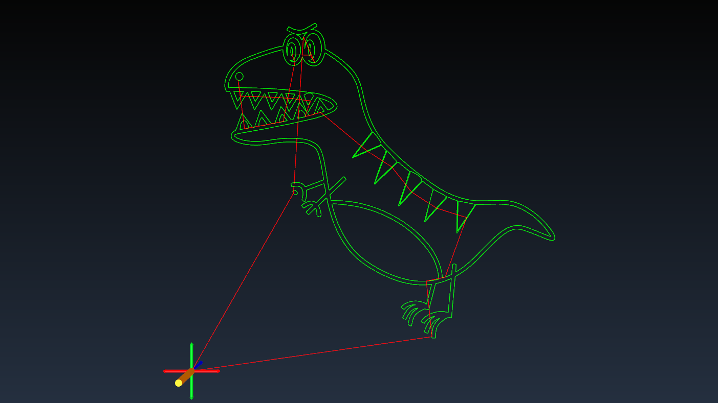 Screenshot from the OpenSCAM simulation
If you want to have a look at the G-code file, it's available here.
Screenshot from the OpenSCAM simulation
If you want to have a look at the G-code file, it's available here.